CAVE BUG: A CV1000 Game Swapping Solution
With how easy it is to get a CV1000 PCB nowadays due to bootlegs popping up, Ive been more confident playing around and modding the hardware without the guilt of playing with somewhat rare original PCBs. So this month I began developing a simple solution for game swapping.
The CV1000 has basically no security, the hardest part to converting the game is de-soldering the chips. After that you can re-flash and reinstall the chips to convert. Obviously de-soldering, reprogramming and soldering the chips back on isn’t very fun so I wanted to come up with a cartridge based swapping system.
The general idea is as follows: 1) Create a “parasite” thin pcb with the same footprint as a TSOP48 chip that replaces the flash roms on the PCB. 2) Create a daughter board (or set of daughter boards) where the flash roms are installed, these PCBs can be connected to and removed from the parasite PCBs easily.
Repeat step 2 until you have the games you want on their own set of “carts”.
If you don’t value your time to build these, the idea is extremely simple and pretty affordable.
- 3 x 32mb NOR flash
- 1gb NAND flash
- 4 pairs of board to board connectors
- PCB fabrication costs
The most expensive part is the PCB Fabrication due to thin flex PCB costs. Even more if you pay for assembly, which is preferred but unfortunately costs way to much. There were very high engineering fees because of the small size of the flex PCBs, to install just 1 connector on 5 PCBs. For a tiny scale prototype run I couldn’t justify it.
In the end I decided to go without assembly and bought myself a small hotplate, the MINIWARE MHP50. While the upfront cost of this could’ve covered the assembly fees, it definitely paid for itself as I ended up using the hotplate quite a lot on this and other projects.
Anyway, I ended up designing and a ordering a few PCBs and waited patiently for them to arrive.
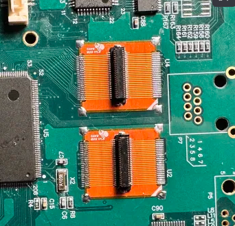
Looking pretty snazzy! I was very happy with the small flex pcb but soldering the connectors to these pcbs was very hard, even with the hot plate. Eventually I was able to get 2 pairs made, 1 each for the program and GFX roms, and could begin testing.
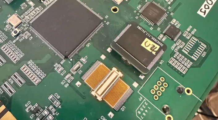
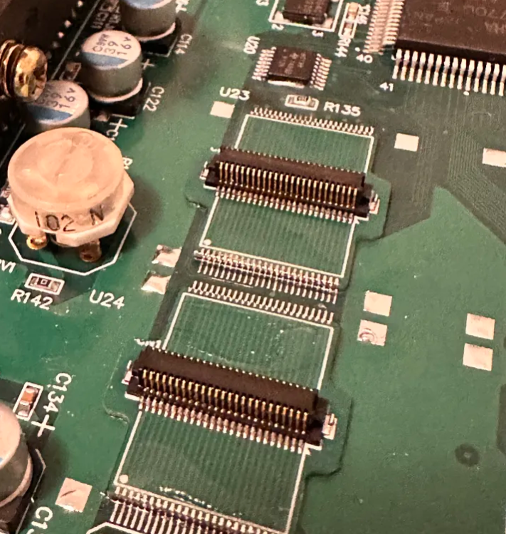
Installing the flex PCB was extremely easy, much easier than the original flash chips. The pcb was designed with small vias in pad, with pads on both side of the PCB This allowed solder the flow freely between both layers and made a very good bond to the original flash footprint. As an extra precaution I also used some thin heat resistant 3M double sided tape on the underside when installing, to ensure the PCB isn’t lifted when removing the daughter board. There isn’t much force required to remove them and I doubt any damage would ever occur, but even though this is a bootleg its still expensive and didn’t want to risk it.
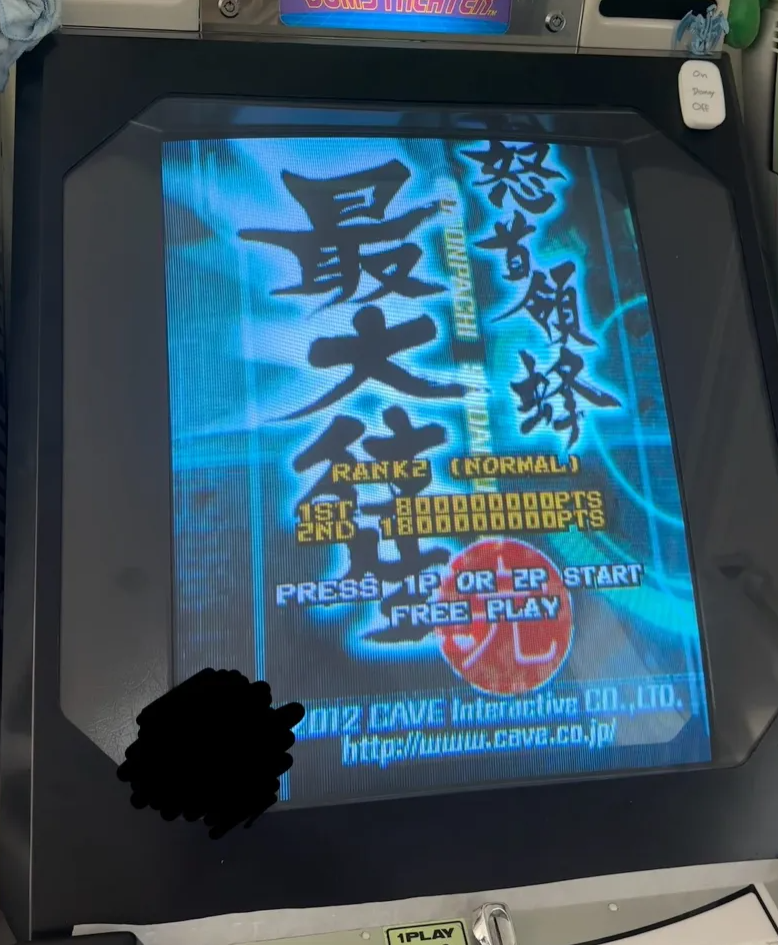
And would you look at that, it works! I hadn’t installed sound yet but I was able to play through a credit and confirm everything behaved as expected. Once I got around to doing the install for the sound roms I started to encounter reliability issues. The connectors I had chosen weren’t very good and you could tilt the PCBs very easily, causing a bad connection resulting in ear piercing sound corruption. Because of this I found a new more reliable and affordable connector to use, and designed my 2nd revision.
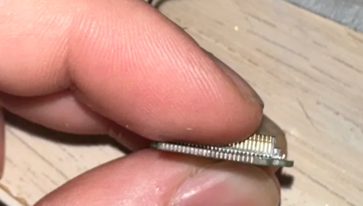
Because I struggled with assembly so much the first time I opted to get very thin FR4 pcbs made rather than flex this time, so that I could get cheap assembly. This was a dumb idea and made installation on the PCB 100 times harder. Because I used FR4, the pcb was too thick for the solder to flow freely between to top and bottom pads. This made installing them on the CV1000 much harder, where I had to resort to very accurately sanding the edges of the pcbs to make castellated edges. I had an extremely small margin that i could easily miss if i sanded to much.
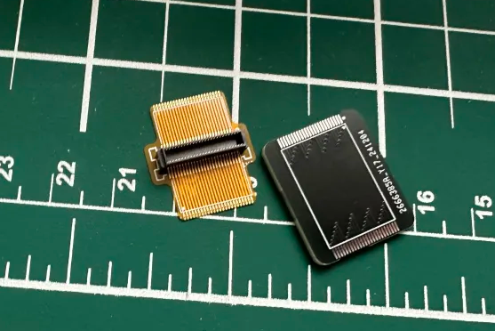
Now that I had everything installed, I was able to connect all the flash chips on and boot it up for one final test. Sure enough everything worked including sound. I was no longer getting the awful audio corruption. I was very pleased with this result and went ahead and designed my final parasite PCB. This time would go back to using the flex pcb option and decided I would just suck it up and learn how to reliably assemble these using my hotplate. This one now anchors to the surrounding ground pads to help with alignment. I’ve dubbed this pcb the “Cave Bug”.
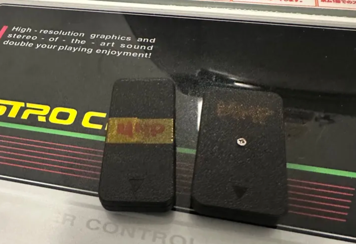
I also quickly threw together a small pair of shells to encase the daughter boards, 1 for the sound chips and the other that holds the program and graphics flash.
And that’s it for now. I’ll be testing the entire CV1000 library with this setup.